

This project started with a simple question: how do you model the motion of a ride robot in a way that is accurate enough to study, but still practical to build and validate in a semester? I focused on the KUKA KR500 R2830 as a stand-in for ride-style KUKA RoboCoaster systems, derived the forward and inverse kinematics, checked the math against RoboDK, and wrapped everything into an interactive motion-planning app.
The full paper is more mathematical than this page, but the core story is straightforward. I simplified the larger ride platform into a fixed-base 6-DOF arm, solved the pose relationships analytically, verified the results at machine precision, and used those same solvers to drive waypoint-based MoveJ and MoveL planning.
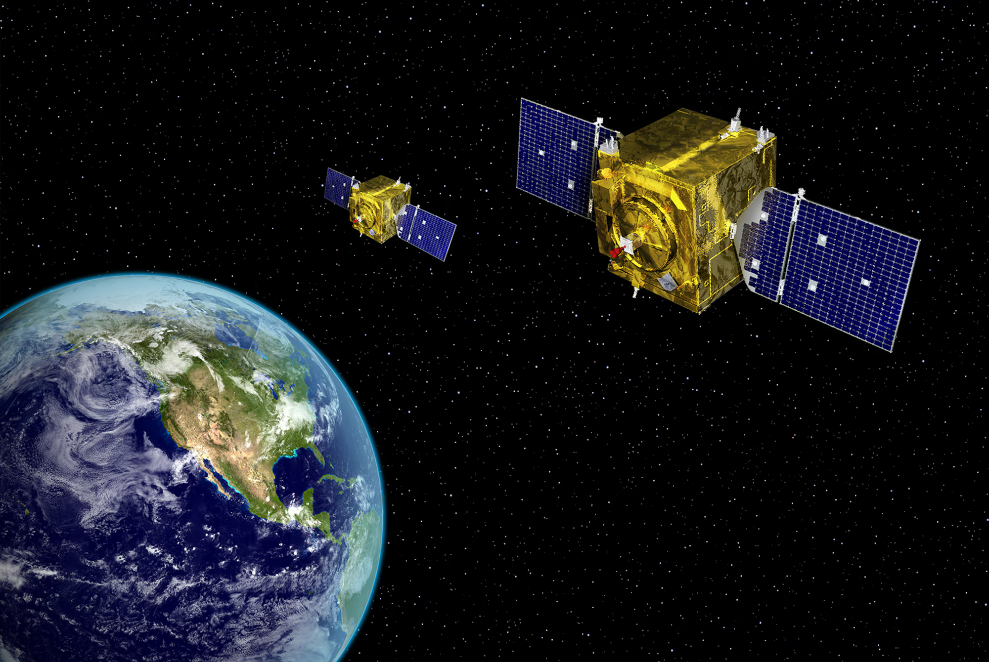
Theme Park Context
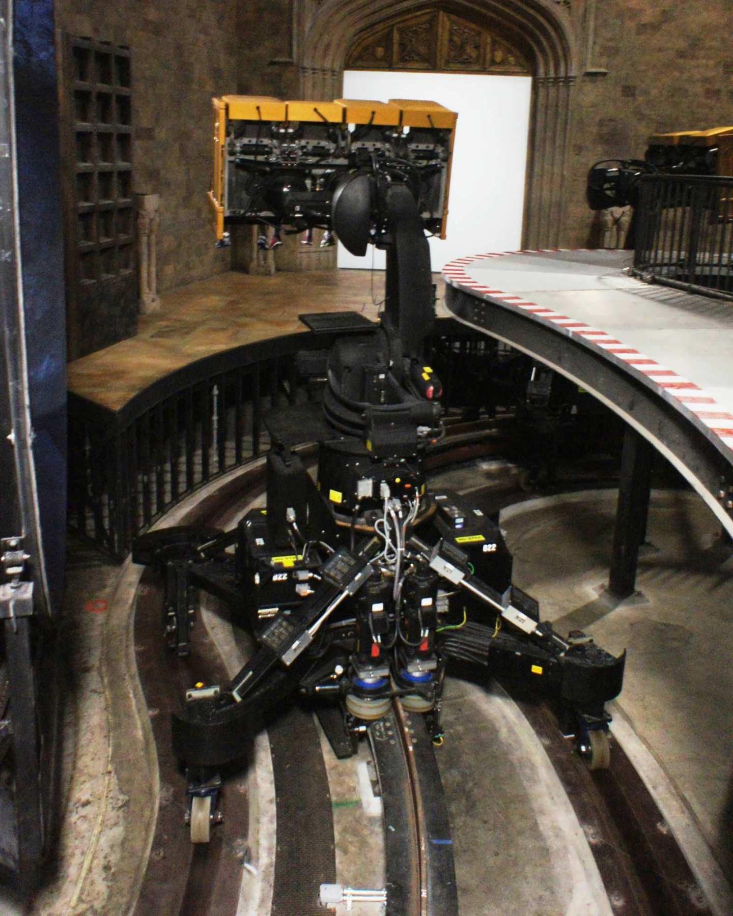
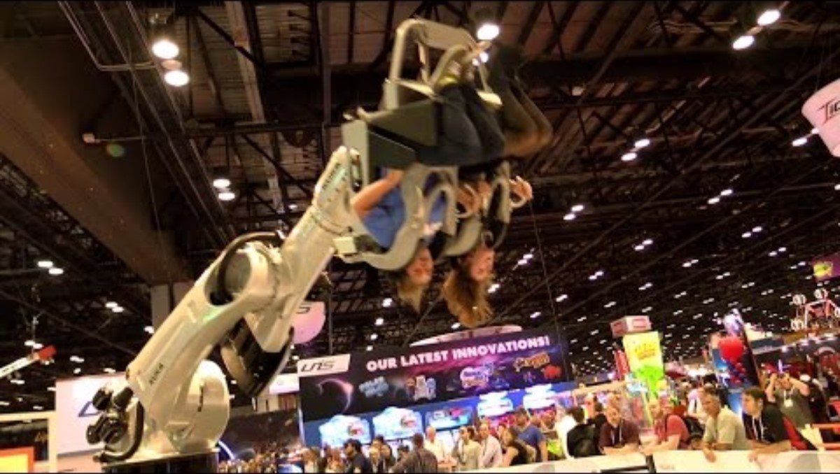
The project was motivated by amusement ride robotics, especially systems that use large KUKA arms to move riders through tightly controlled motion profiles. Real ride installations can include a mobile base, proprietary hardware, and platform-specific geometry, so I reduced the problem to the robot arm itself. That made it possible to derive the kinematics cleanly while still keeping the work tied to a believable ride-robot use case.
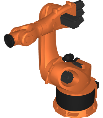
Why the KR500 R2830?
The dedicated RoboCoaster variants do not expose much public geometry, so I used the KR500 R2830 as a close proxy. It is large, industrially realistic, and most importantly it has a spherical wrist, which makes a closed-form inverse kinematics solution possible.
What was simplified?
The real ride architecture can include the rider carriage, a platform, and sometimes a mobile lower structure. In this project, the arm was treated as a stationary serial manipulator so the FK, IK, and planning logic could be isolated and validated first.
Robot Model
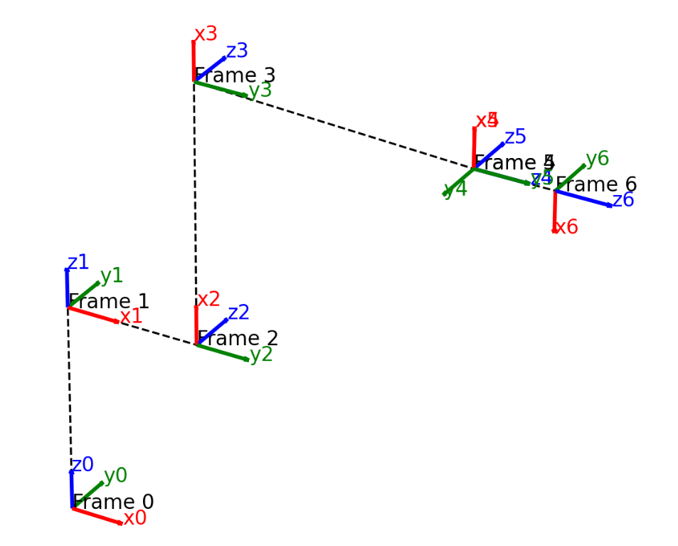
The paper defines the robot as a 6-DOF serial manipulator with a base frame {0}, tool frame {6}, and intermediate frames assigned using the modified Denavit-Hartenberg convention. The pose map is written as a homogeneous transform from the base to the tool frame:
To match the reference convention, the effective joint angles were offset and signed before building the transforms:
| Joint | ai (mm) | αi (rad) | di (mm) | θ offset |
|---|---|---|---|---|
| 1 | 0 | 0 | 1045 | 0 |
| 2 | 500 | -π/2 | 0 | 0 |
| 3 | 1300 | 0 | 0 | -π/2 |
| 4 | -55 | -π/2 | 1025 | 0 |
| 5 | 0 | +π/2 | 0 | 0 |
| 6 | 0 | -π/2 | 290 | +π |
Forward Kinematics
The forward-kinematics chain is the backbone of the whole project. Each link transform is built from the modified DH parameters, and the final pose is obtained by multiplying the six consecutive transforms:
One of the helpful shorthand terms in the paper is the scalar B, which collects the radial reach of the first three joints:
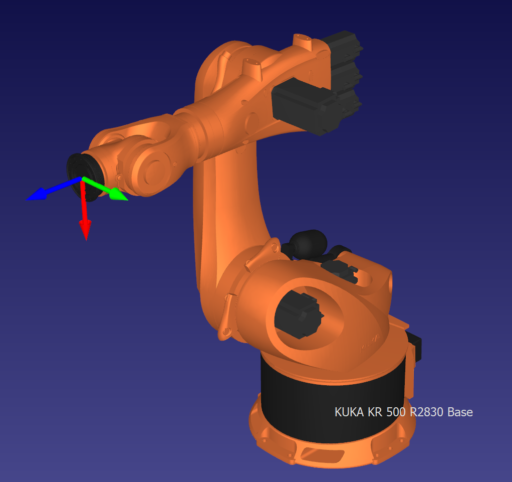
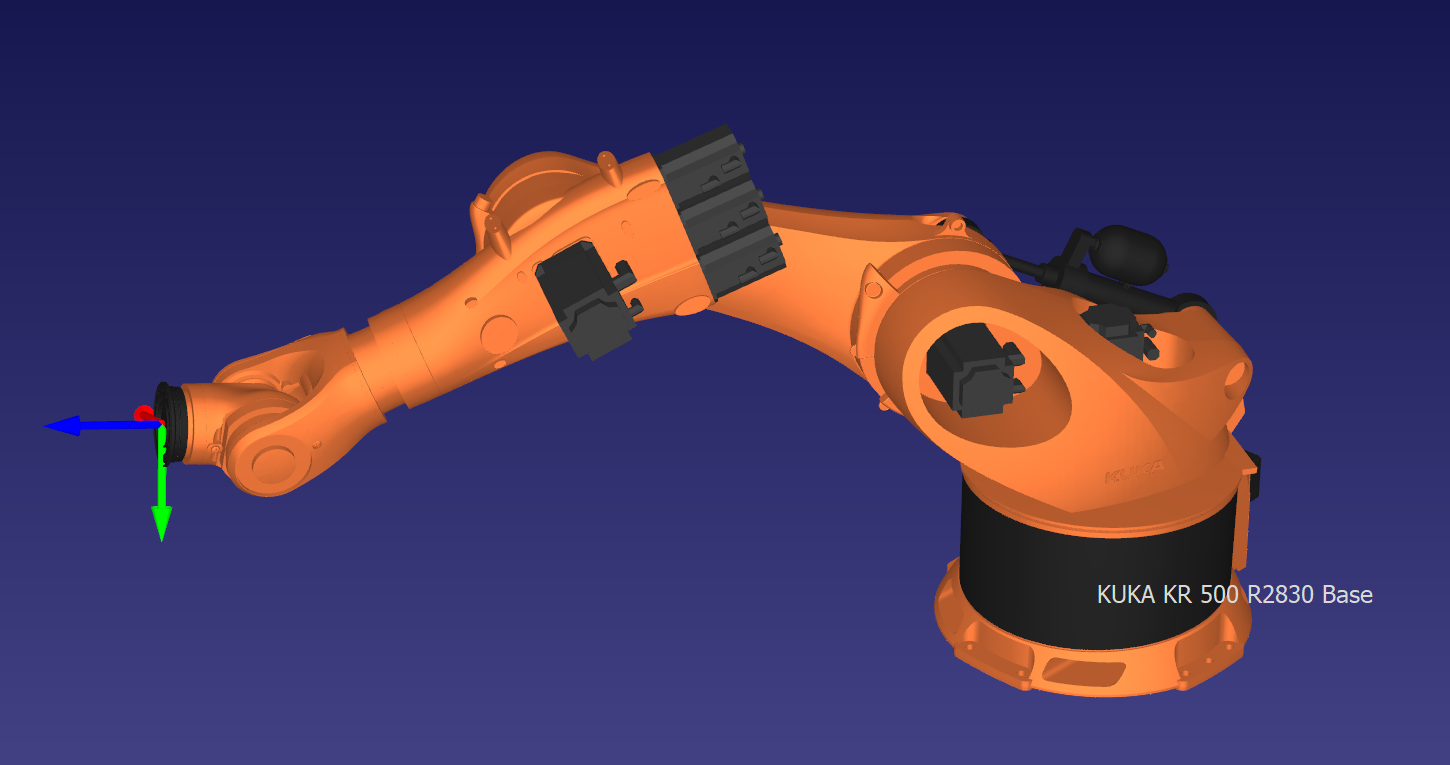
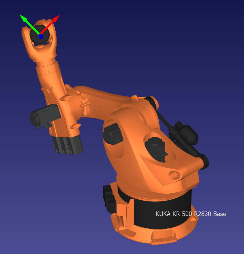
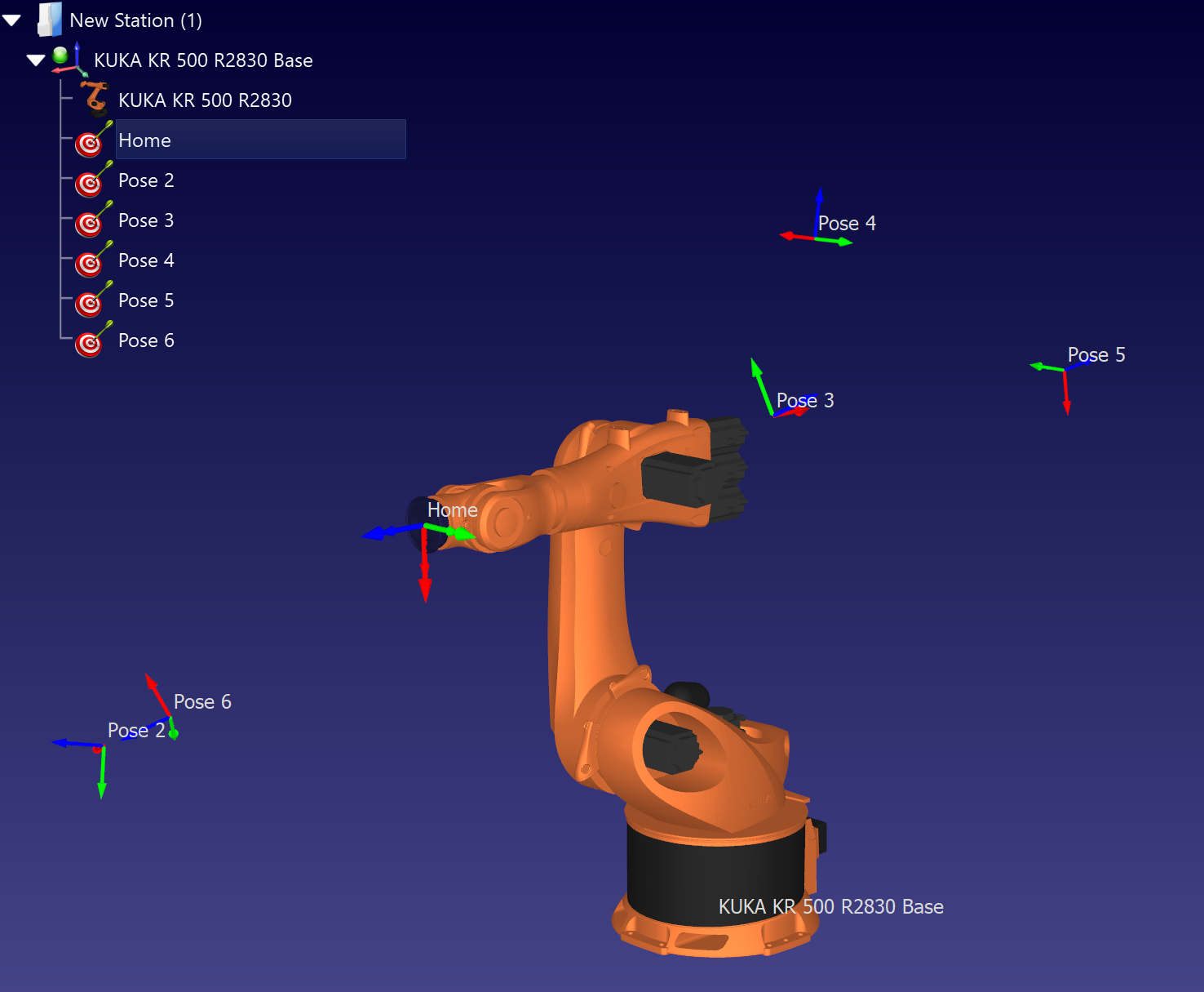
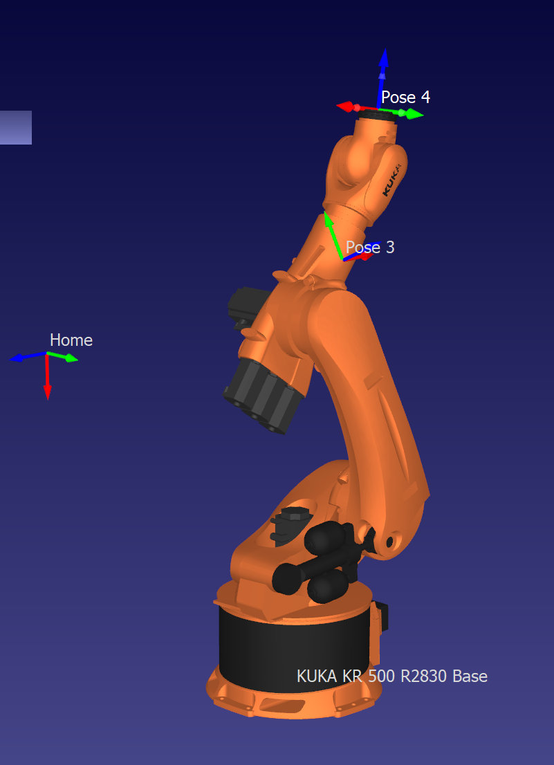
Rather than stop at symbolic work, I checked the implementation against RoboDK. The representative configurations below match to numerical precision, which gave confidence that the frame assignment and sign conventions were correct.
To quantify the agreement, the paper compares both position and orientation residuals:
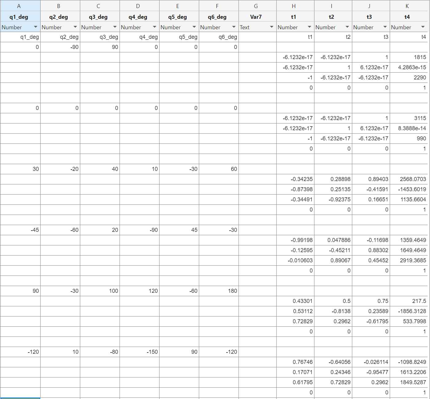
The full MATLAB export used for the FK spot checks is shown below. It includes the joint inputs and the resulting homogeneous transforms for the representative cases highlighted in the paper.
Analytical Inverse Kinematics
The inverse-kinematics result is the part of the project that made the motion-planning app practical. Because the KR500 uses a spherical wrist, the IK can be split into two stages:
Position stage
Solve q1, q2, q3 from the wrist-center location. This reduces the first half of the robot to a planar geometric problem with shoulder and elbow branches.
Orientation stage
Solve q4, q5, q6 from the reduced wrist rotation. This is where the flipped wrist branches appear, unless the robot is near a wrist singularity.
The wrist center is found by backing out the final flange offset from the tool pose:
The paper also enforced joint-limit filtering after each candidate solution. The limits used in the model were:
| Joint | Allowed range (deg) | Role in the solution search |
|---|---|---|
| q1 | [-185, 185] | Shoulder branch filtering |
| q2 | [-130, 20] | Upper-arm reach filtering |
| q3 | [-100, 144] | Elbow branch filtering |
| q4 | [-350, 350] | Wrist rotation wrapping |
| q5 | [-120, 120] | Singularity-sensitive wrist tilt |
| q6 | [-350, 350] | Tool-roll wrapping |
IK Verification and Branch Behavior
I verified the analytical IK with a round-trip check:
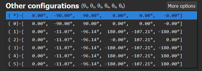
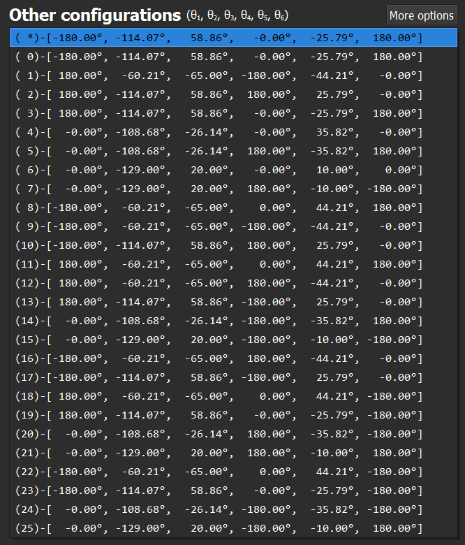
The three representative results from the paper are summarized below.
| Case | Test pose q (deg) | Returned solutions | Worst reported error |
|---|---|---|---|
| Home | [0, -90, 90, 0, 0, 0] | 3 | 10-13 mm, 10-6 deg |
| Moderate pose | [30, -20, 40, 10, -30, 60] | 4 | 10-12 mm, 10-6 deg |
| Full-branch case | [0, -129, 20, 0, 10, 0] | 8 | 10-12 mm, 10-6 deg |
The complete MATLAB summary covered 18 test cases. Every case recovered the target pose to numerical precision, and the original configuration was recovered up to angle wrapping and joint-limit conventions.
Interactive Motion-Planning App
Once the FK and IK were working reliably, I integrated them into a lightweight planning app. The interface accepts two waypoints as either joint angles or Cartesian poses, solves the necessary IK, and animates the resulting motion while plotting the joint histories.
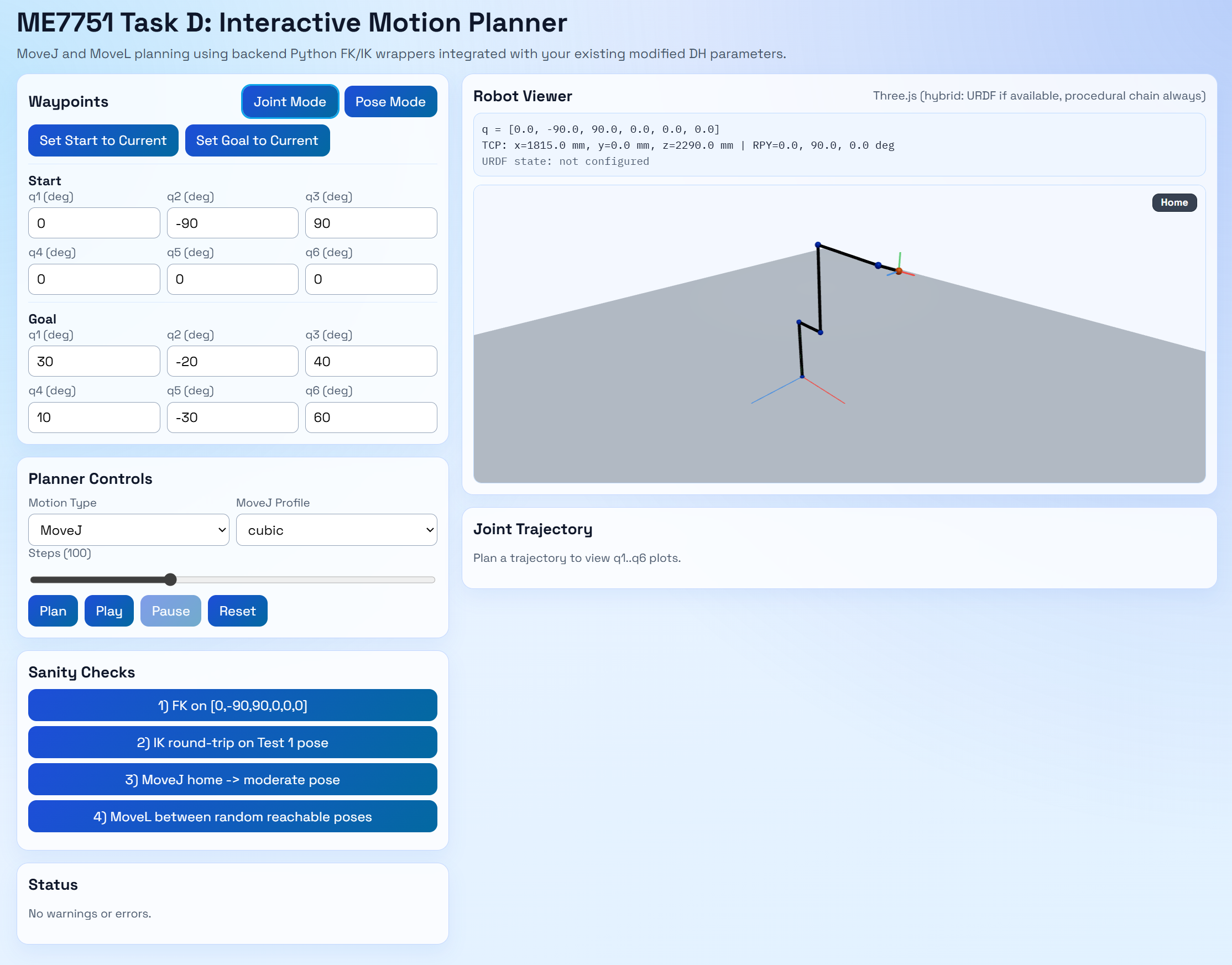
The app supports two motion styles:
MoveJ
Interpolate directly in joint space. This is usually the more straightforward option and is good for quickly checking feasibility and branch continuity.
MoveL
Keep the tool position on a straight Cartesian path while interpolating orientation smoothly with matrix log and exponential operators.
When multiple IK branches exist at a sample, the planner keeps the motion continuous by selecting the feasible branch closest to the previous one:
Outcome and Next Steps
This project gave me a full end-to-end view of ride robot modeling: define a believable robot proxy, derive the kinematics, verify them against a simulator, and then use those same tools inside a planning interface. The final result is not just a set of equations on paper, it is a working workflow for evaluating pose reachability, branch selection, and motion feasibility.
The main future directions from the paper and presentation are:
- Build a more robust simulation package around the same FK/IK core.
- Find or create a usable URDF for the KR500 geometry.
- Bring the mobile lower ride platform back into the model.
- Build a scaled physical version with 3D-printed hardware.
If you want the full derivations, detailed validation screenshots, or the app source, the paper and repository linked above are the best places to go deeper.
