

The goal of TERRASat is to launch a small satellite (12U CubeSat) equipped with atmosphere breathing electric propulsion and instruments to measure magnetic fields. The satellite will be launched from Earth to Mars and will orbit Mars to monitor localized magnetic fields around craters with high resolution using AI to focus on areas of interest. This is important because magetic fields have been linked to signs of water, activity, and potentially life on other planets. This project revolutionizes how we treat data aquisition and scientific exploration of space!
Mission Architecture
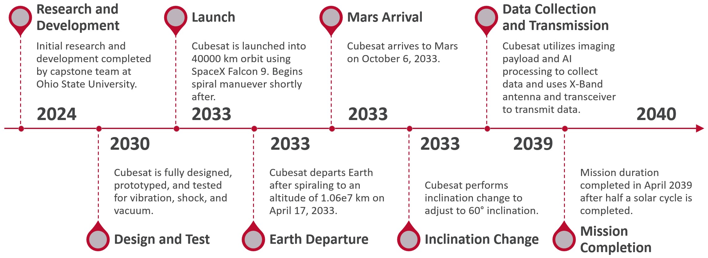
The full mission timeline for this project can be found in the image below. Currently, we are performing in-depth R&D to model, simulate, and research optimal CubeSat designs for this mission to Mars. The design and formfactor have been finalized and we are beginning to refine the orbital mechanics analysis, minor CAD components, and use of equipment/instrumentation during the mission. An up to data interface control document (ICD) is in the works to define the sensor input formats, voltage levels, mechanical mounts/mechanisms, and thermal interfaces. Additionally, I am performing system-level risk analysis on each componenet of the satellite. Looking at qualitiative (failure modes effects & criticallity analysis - FMECA) and quantitative (probabilisitc) assesments will become important in identifying and mitigating potential issues on-orbit.
Once the fully designed CubeSat is prototyped and vibration, shock, and vacuum tests have been performed, we plan to launch around 2033. The overall mission duration for this satellite is currently no longer than 7 years. We are exploring ways to extend that with potential on-orbit servicing for future instrument and equipment improvements.
CAD Model
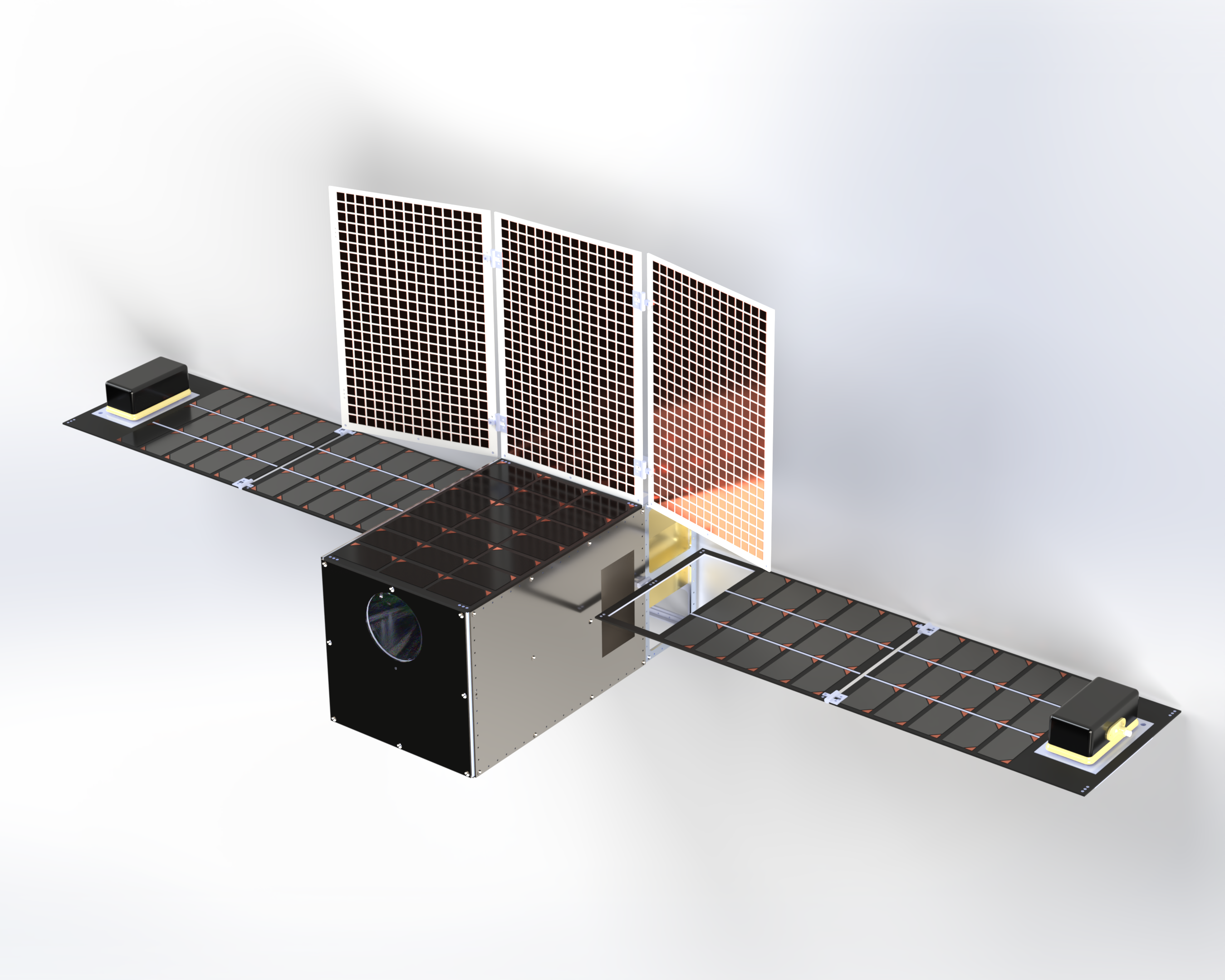
A finalized version of the model for TERRASat can be found below. The specific components are discussed in more detail as well. The design consists of a maximized solar panel array with 4 “wing” panels and 1 central top panel array. The deployable X-band antenna will be used for communications, signal/data transfer, and other operations from Earth. Additonally, the 4U detachable interplanetary propulsion system (IPPS) on the back of the CubeSat will be used to accelerate the timeline of the transfer to mars. TERRASat will launch aboard a SpaceX Falcon 9 rocket and spiral out before the IPPS system fires continously (discussed more in the orbital mechanics section).
When stowed, TERRASat conforms to a 12U format and adds minimal extra dimensions that are withing the payload tolerance standards of the Falcon 9 rocket. The magnetometers seen on the solar panels of the CubeSat are safely secured inside of cutouts in the main hull during transportation. These will extend when on-orbit.
Components
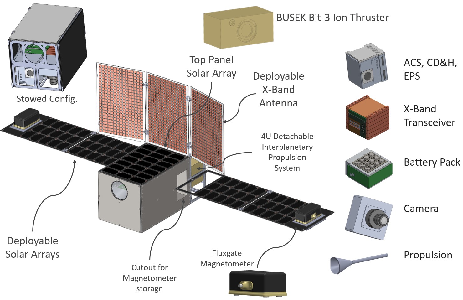
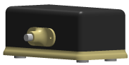
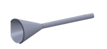
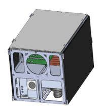
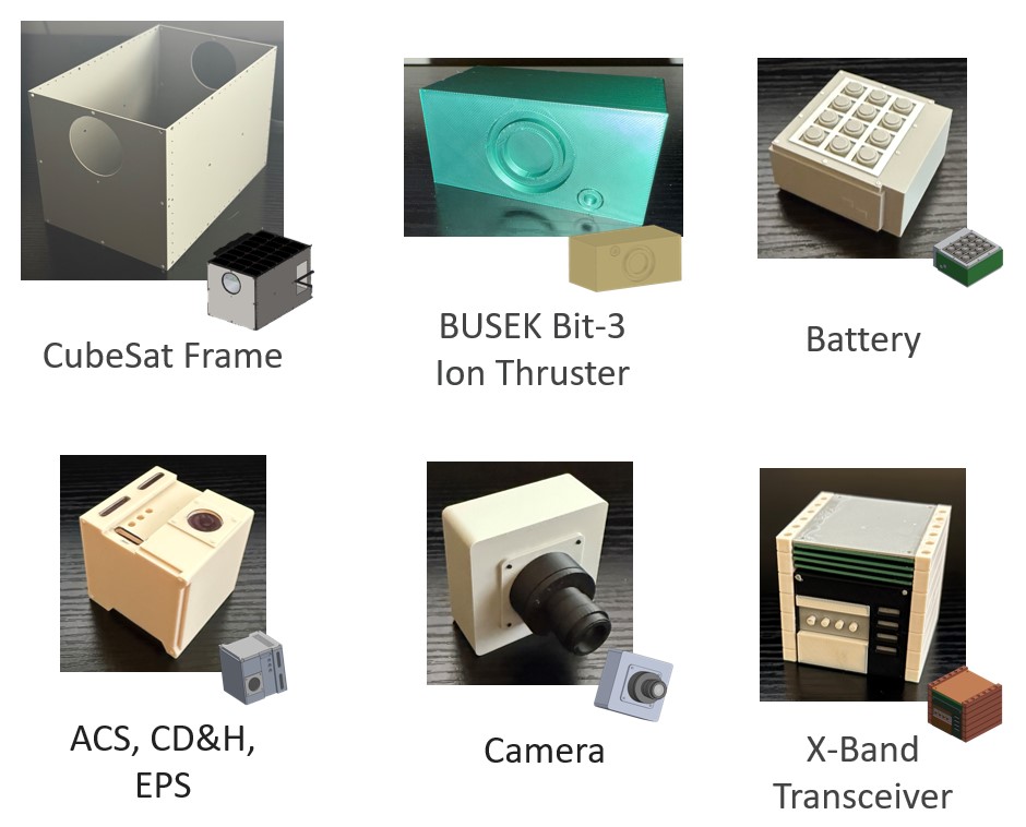
The internal component CAD of TERRASat can be seen below. The attitude control system (ACS) is responsible for maintaining the positioning of the satellite while on-orbit. The command and data handling subystem will control the spacecraft, manage internal data flows, and handle the data transmitted to or received from other systems. The electircal power system (EPS) manages the power collection and distribution in the satellite with an integrated Battery Management System (BMS). The X-band transeiver will handle the transmission and reception of radio signals within the X-band frequency range, which is approximately 8 to 12 gigahertz (GHz). The battery is a standard component of the BMS. There are several of these battery packs lined up inside of TERRASat. The camera is the primary unit used to capture images of Mars surface and convey important qualtitative data to the team on Earth. The IPPS system is a BUSEK Bit-3 Ion Thruster that provides the propulsion necessary to meet the mission timeline for Mars transfer. Additionally, the magnetometers are MAVEN Fluxgate magnetometers that are places on the edges of the solar panels when deployed. Finally, the airbreathing electric propulsion system (ABEP) is modeled as a cone and pipe (for now…this is still an area of exploration!).
Instrumentation
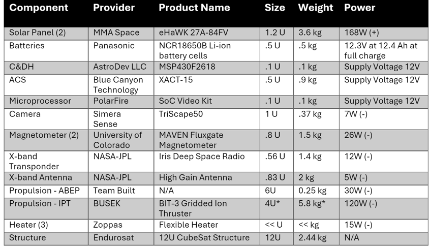
Details about the instruments described above can be found in the table below.
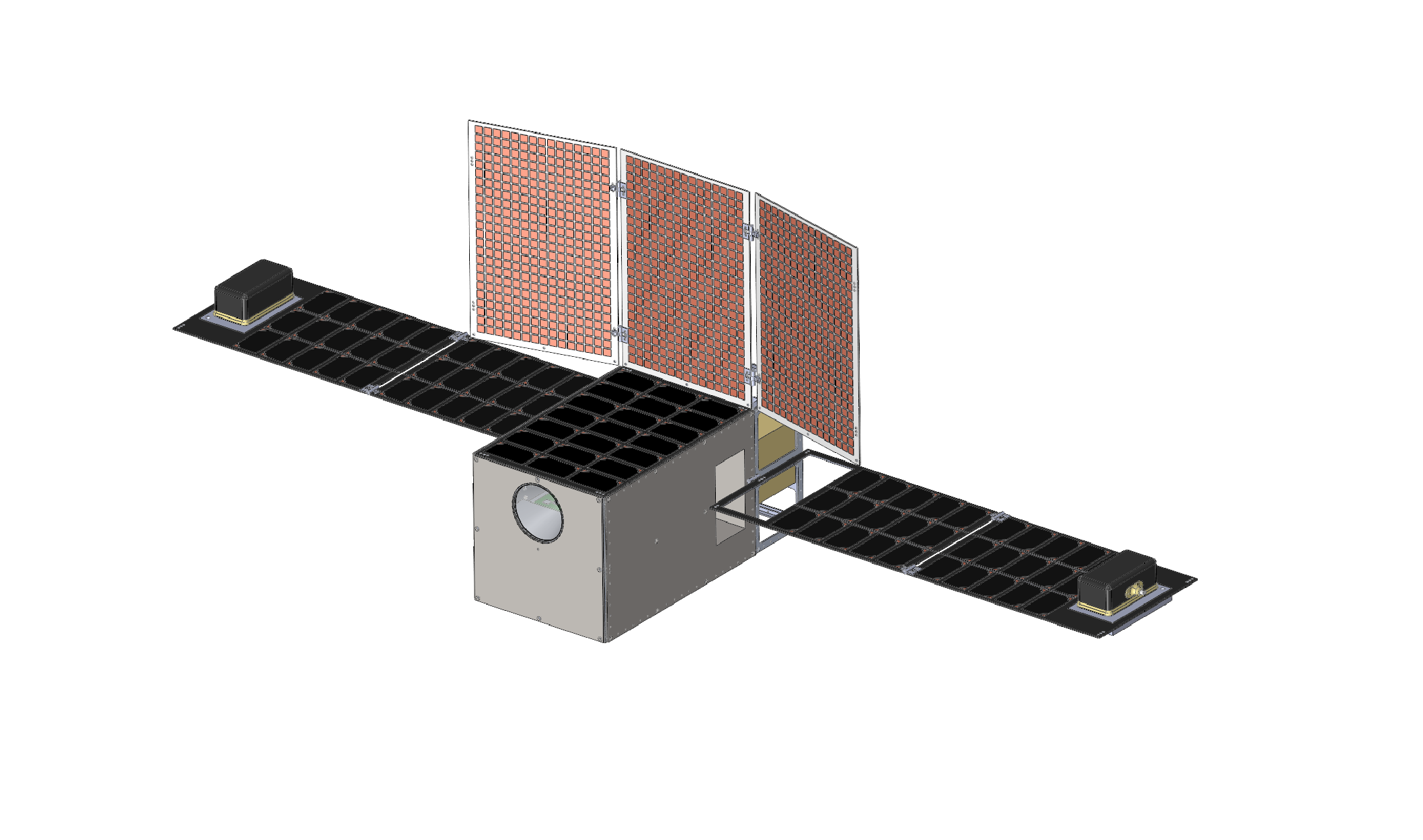
Stowed Configuration
Below is how the CubeSat would look when it is in the stowed configuration.
3D Printing & Prototyping
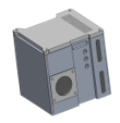
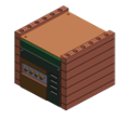
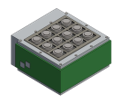
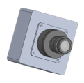
To get an initial idea as to the true sizing and clearance of certain parts, I decided to 3D print the full design and components at 50% scale. The overall size (end to end) of the CubeSat fully deployed is approximately 2ft at 50% scale. Below is each subsystem component with their respective 3D print. The full model was assembled, with panels, but has unfortunately been lost (somewhere at the Region III AIAA conference) and a future iteration will need to be made. I hope to recreate these prints with a more modular and functional design for testing of ease of use.
Structural Analysis
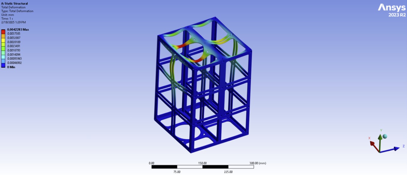
A basic acceleration test on the 12U frame is shown below. We are still working on results with this, but initial estimates show no immediate sign of problems with the overall structure.

Specifics on Propulsion System
Interplanetary Propulsion Subsystem
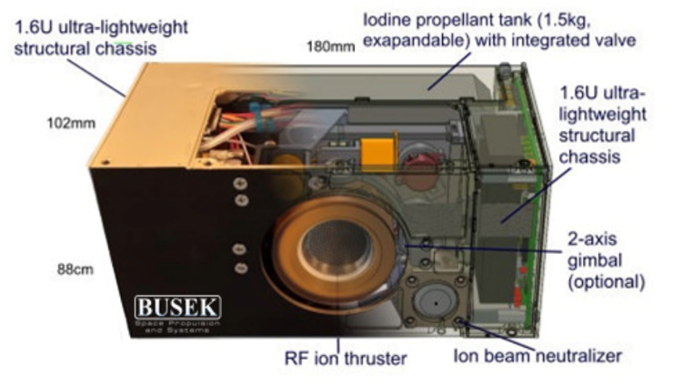
The IPPS attaches to the CubeSat with four Dcubed pin pullers for detachment after use. This will reduce weight and simplfy the overall system once inserted into orbit around mars. The system is a BIT-3 Gridded Ion Thruster with integrated propellant storage. It has an ISP of 2150 s and only weighs about 1.4kg with a gimbal! The target power input for this subsystem is approximately 60 W.
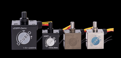
The pin pullers have been validated and are at a technology readiness level (TRL) of 9. They are 17 cubic millimeters and 12 grams with a listed shear load of greater than 50N.
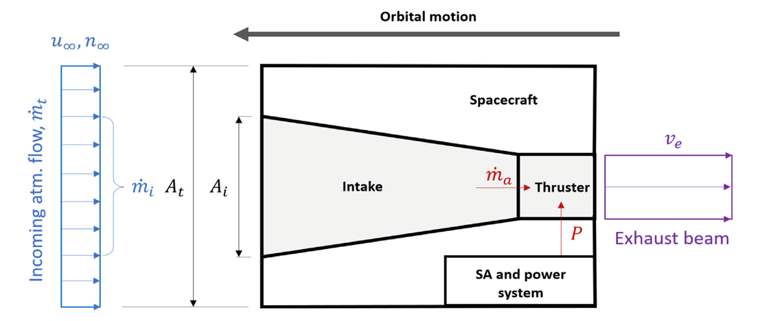
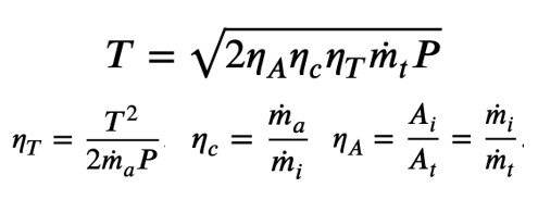
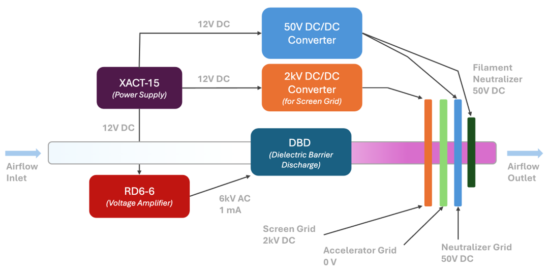
Air Breathing Electric Propulsion Subsystem
The ABEP system uses dielectric barrier discharge (DBD) for the plasma generation. It utilizes a 3-grid system for ion acceleration and 3 DC/DC conversions for the screen and neutralization grid. It also uses an RD6-6 DC/AC voltage amplifier for the DBD system.
Orbital Mechanics
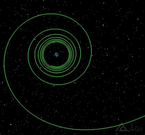
Phase 1 - Earth Departure
The mission design and orbital mechanics were created using Ansys Systems Tool Kit (STK). To reduce the overall delta V needed for Earth departure, a spiral out manuever was chosen. Our team was able to optimize the transfer to only consume approximately 3.6 km/s! The transfer would occur over 4 days and begin on April 13, 2033.
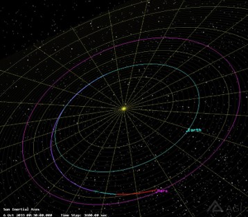
Phase 2 - Earth to Mars Transfer
Once we have spiraled far enough out from Earth’s sphere of influence, we will begin a continous burn of the low-thrust IPPS. The transfer will begin on April 17th, 2033 and take approximately 4-5 months (due to IPPS continous firing). This is still an area of research for us right now, but we expect the total delta V for this manuever to be less than 5.6 km/s.
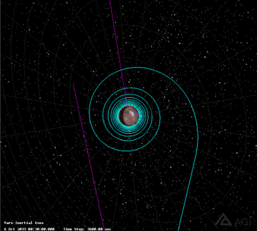
Phase 3 - Mars Arrival
The final manuever (before circularizing) will be a spiral in manuever when approaching Mars. After many extensive analysis, we have found that this achieves an optimal delta V solution. While all options are being considered, this approach is what is currently implemented in the mission architecture. The duration of the manuever would be approximately 4 days and consume no more than 2.3 km/s of delta V.
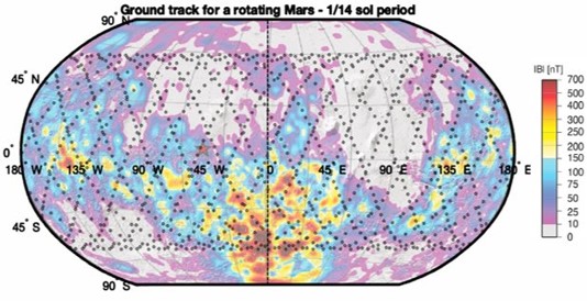
Mars Ground Track
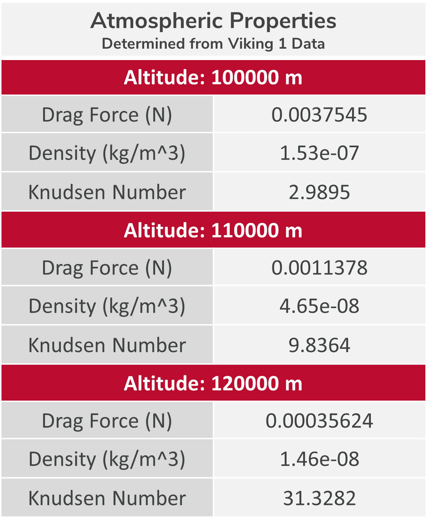
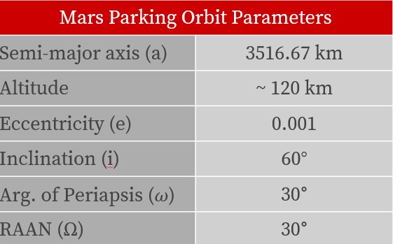
It is important that we design our orbit over Mars to pass through the known areas of high magnetic fields. For that reason, we use a parking orbit that is highly inclined. See the images below for details on the orbit parameters. The repeatability of the orbit should give a good variety of magnetic field points to collect and average the most amount of data. Additionally, to collect the highest resoultion data and to use the ABEP system, we chose an altitude of approximately 120 km around Mars.
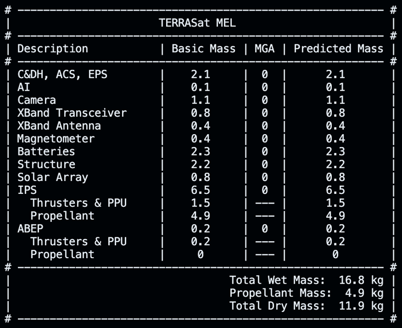
Minimum Equipment List (MEL) & Concept of Operations (CONOPS)
The updated CONOPS for this mission shows a total delta V burn of approximately 7.3 km/s. This allows us to estimate about 4 x 1.5 kg of solid Iodine propellant packs needed for the IPPS.
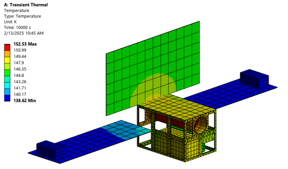
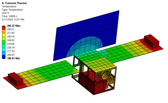
Initial Thermal Model
An initial thermal model for TERRASat was created in Ansys Thermal Desktop. This is a simplistic transient thermal model that demonstrates the interaction of the satellite under nominal conditions (not in direct sunlight) and the space environment. Based on averaged 120 km data from Pathfinder and Viking 1, the enviroment was modeled with an initial temperature of 130.4 K. The image on the left shows how without heating the magnetometers, they can reach dangerously low temperatures for operation. The radiation of the outer surfaces (frame, solar panel, and antennas) seem to be enough to keep them relatively warm based off their individual material emissivity. When 3 Zoppas flexible heaters are added to the coldest components, the minimum temperature of the system rises significantly. The heaters have a high TRL and have been proven useful in space applications. They add almost zero additional mass and size to the overall design.
Artificial Intelligence (AI)
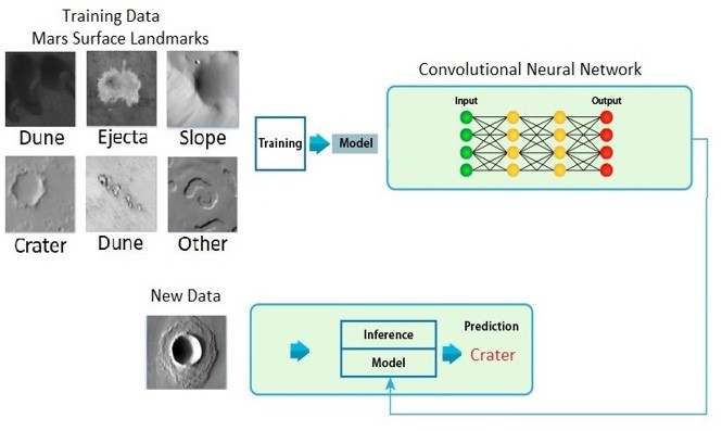
Craters on Mars have been shown to show significant activity of magnetic fields in the past, so accurately identifying craters on Mars will allow for maximized data aquisition opportunities. An AI model was built using a convolutional neural network (CNN) with training data from Mars surface images. The model does a phernominal job at determining craters on Mars. The camera on TERRASat will be used in conjuction with this AI model to adjust our orbit based on the desired area of interest. The general layout for the AI model is below.
Budget
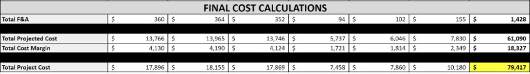
We expect TERRASat to cost approximately $79.4M from project start to end. This uses a 30% cost margin on top of the projected cost of the project (standard for NASA projects). The budget needs some refinement to see if cost can be reduced in high pass areas. Also, the final vendors and manufacturing locations need to be determined before a full budget is presented. We are working on this now and expect to complete this before the International Astronautical Congress (IAC) conference in September.
Updates
March 28, 2025 - Our abstract for TERRRASat has been accepted at the International Astronautical Congress (IAC) conference in Sydney, Australia this September!! We are extremely excited to be presenting our work at this technical conference and look forward to meeting so many great people in the space industry. A BIG thank you to Dr. John Horack, advisor and Neil A. Armstrong Chair in Aerospace Policy for The Ohio State University College of Engineering! Dr. Horacks commitment and assistance in this project has had a profound impact on our success. Congratulations to all of my follow student engineering teammates as well (Jessica Sillus, Ian Harris, Annabelle Zerby, Stephanie Small, and Svitlana Pryymachuk!

)